Astronomy cameras, especially CMOS-based ones, bristle with features and different controls and all affect the image data that they produce in some way or another. One might think of sensor gain (or on DSLRs, ISO) as one of the most prominent and critical controls for a camera of any sort, and rightly so given what it does. But gain often has a far less familiar companion called offset that, to many, appears to be related to gain in some fashion but how it works and its exact relationship to gain is mysterious and not very obvious. This post aims to explain offset and its relationship to gain as well as how to determine just what is a good offset setting to operate a camera at.
First, if you are completely and utterly unfamiliar with the concept of sensor gain and offset, Jon Minnick of Cloud Break Optics (Seattle’s finest astronomy superstore) wrote a very good article on gain and offset as part of a multi-part series on astrophotography. I suggest you start with that and then follow up with this.
Offset seems to be quite mysterious to most people, and for good reason. None of the typical performance graphs you see with cameras describe or measure it in any way, and camera and sensor stats might give it a passing reference at most. Yet there it is, a slider or input field labeled “Offset” and always positioned next, or at least close to, gain. So what is it and why should I know what it is?
Offset is exactly as its name implies: it is an offset that is applied to the histogram curve which shifts it – offsets it – farther to the right on the histogram by some amount. This ensures that the minimum value that any pixel might record is not underexposed and is therefore clipped in the blacks. This is especially important in astrophotography because of the nature of it – some pixels on the sensor might be positioned to look at purely dark space and therefore will collect far, far fewer photons than pixels that has the light from a star, nebula, or other light-producing object pouring into it.
Avoiding clipped-black pixels means that you avoid having pixels with insufficient signal or, worse, a value of 0. This is the opposite predicament of an image that has pixels that are clipped-white. Both types of clipped pixels effectively have no data that can be meaningfully acted upon during processing.
Demonstrating and determining offset
I like teaching by example, so we will learn how to observe the effect of offset in an applied sense and learn how to determine what constitutes a “good” offset setting to use, regardless of a camera’s vendor or model. Before we dive in, I want to make a specific point about terminology around offset. There is no such thing as an “optimal” offset. I know that in our field it is second nature to want to find the optimal or perfect setting for a given parameter in a specific situation, but that’s not really the case with offset. Instead, you should ask whether or not you have sufficient offset, as there is some subjectivity here.
To find this sufficient offset, you will want to use camera control software that can control the camera using native camera drivers. This allows for direct and interactive control of the camera’s offset setting. Personally, I use the excellent SharpCap program for this, but any other program that provides real-time image capture using native drivers and offers a histogram that can be inspected at a critical level will work. Fire Capture is another such program.
The camera I am using in my examples is a QHY183M. According to the Gain per e-/ADU measurements that are supplied by the vendor, I should use this particular camera at a gain of 10 which is unity gain for this camera, where one electron (e-) equates to 1 point of ADU:
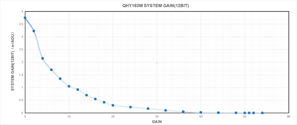
Unity gain is a great gain level to operate at. But what about offset? Should I set it to 0? 100? 42? Below is how I will answer this question.
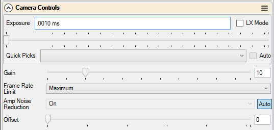
First, cap off the camera to make sure that no light can reach the sensor, exactly as you would when creating dark or bias calibration images. Cooling is not needed for this, so that can be kept off, if desired. Connect to the camera in the program you’ve chosen, and set it up in with the following parameters:
- Expose at the shortest possible exposure time
- Gain is set to the level which you intend to operate the camera at
- Offset set to 0
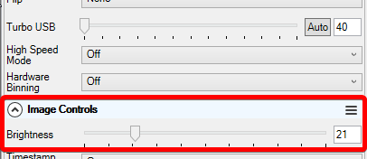
ZWO (and possibly other) users: For ZWO cameras, SharpCap calls the offset setting Brightness and it is located in the Image Controls section, not the Camera Controls section, as it is for QHY cameras. This might be the case for other brands of cameras as well. If you know that your camera has an offset knob to turn but you can’t immediately find it in SharpCap, search (or ask) around.
OSC camera users: In general and in SharpCap, it is best to do this exercise with the camera output set to RAW16 and debayering set to off. This makes it so that the histogram displays in the monochromatic realm and doesn’t display the individual R, G, and B channels, which can make things confusing. We are interested in the raw pixel array, after all.
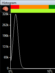
Next, open up the histogram display (in SharpCap: Tools > Histogram) and make it as big as you can. You might notice that it appears empty, but it isn’t. That’s because the curve is likely slammed up against the left side of the histogram with the vast majority of pixels being clipped in the black. This is what we aim to remedy using offset.
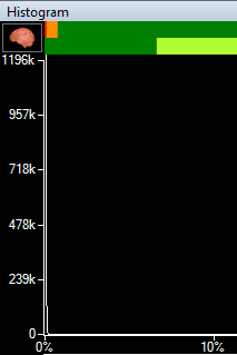
With today’s really clean and ultra-low read noise back-illuminated CMOS sensors, one can barely perceive the histogram curve, but it is indeed there. This is why I suggest maximizing the histogram window as there is no zoom function for the histogram in SharpCap. Viewing the image itself is unimportant for this exercise.
With the camera now set up and displaying the baseline curve, we will now increment offset and observe its effects. You will notice that as you increment its value, the histogram curve (or, spike in this case) will shift farther and farther to the right, up the histogram scale:
The goal here is to increment offset until all parts of the curve, including its gently-sloped base, are well and fully clear of the left edge of the histogram. It’s alright to put some distance between the left edge and the left extremity of the curve, even several hundred ADUs’ worth of space. In my case, I settled on an offset value of 14. It brings the curve well off the edge by about 700 ADU. It is now assured that I will not clip the pixels that receive insufficient signal.
Relationship of gain and offset
We just learned what offset does in practice and how to determine an offset value to use. But what happens when we increase the gain without increasing the offset? The short answer is that we risk clipping the blacks again as increasing the gain will fatten, or widen, the curve towards both ends of the histogram. As gain increases, the left side of the curve will eventually meet the left edge of the histogram again and lowest value pixels will clip. To prevent this, we must increment the offset further to ensure the curve stays off the edge, just as we did above.
The above screenshot illustrates this effect. I kept the offset at 14, but increased the gain to 35. Accordingly, the curve widened and is now very much clipping. To prevent this, I must increase the offset beyond its current value of 14:
Now we are no longer clipping. So if I desired to operate my camera at a gain of 35, I must also increase my offset to somewhere in the vicinity of 45.
You might read about or hear some sources claim that offset never needs to change. That is a misunderstanding of the role that offset plays. The above demonstration exhibits why offset also has to scale up as gain does in order to prevent clipping.
Calibration frame considerations
Just as when you change the gain or operating temperature of the sensor, changing the offset will also require a new set of calibration frames to be generated. This is because changing the offset also changes the mean pixel value of the image.
If you calibrate your images using master calibration frames (master dark, master bias, master flats, etc.) then it’s a good idea to make sure that you record the offset setting along with the gain and temperature into the file names so you do not lose track and get confused. Some applications that offer native drivers for cameras insert an OFFSET keyword, or something like that, in the FITS header and as a file name formatting token.
Configuring offset in applications
Configuring offset in various astrophotography applications may be a bit confusing. There are two general ways that these applications control cameras: through a driver framework such as ASCOM or INDI, or “natively” where the application uses a vendor-supplied software interface (“SDK”) to access the camera.
Because native access to the camera uses the vendor SDK, applications that offer such an option tend to also allow the offset to be configured and adjusted directly in the application itself. However, if you’re using an application that connects to the camera via an ASCOM driver, you might not have control of offset available in the application itself, and instead the offset will need to be configured in a more static sense via the vendor’s ASCOM driver configuration. ASCOM 6.5, which was released in July 2020, adds a driver property for control of a camera’s offset from within the astrophotography application, however camera vendors and ASCOM client application developers would need to update their ASCOM drivers and applications to expose this function to the user.
Excellent article, thank you.
one question, however. The last image still shows curve on the edge despite increasing the offset
Hey Bruce, thanks for the comment. That last image is actually a video. Your web browser should show a > button over it and it demonstrates incrementing the offset to move the edge of the curve off the left side.
Very useful article. Completely corrects my understanding of Gain as an equivalent of ISO but different in approach since it is electronic rather than wet chemistry based; (I am an oldie who grew up on film). Also explained brightness term in SharpCap for ZWO. The interplay between the functions used is poorly explained in many of the forums/texts that I have read through. It is really good to find a well presented description of the functions and the interplay between them.
Thanks for the kind words, William! I’m happy that it helped elucidate the purpose and process behind things.
Very useful article. I understood both offset and gain but not the implications of how they work together. Am I correct in the assumption that, if I know the unity gain of my camera (which I think I can find using SharpCap ‘s sensor analysis), I could set this at the start of the process you’ve described to find suitable offset? Slightly off topic, but, would these gain and offset figures found in SharpCap be the same ones to use in NINA? Many thanks again for your very clear explanation.
Yes, starting with a known gain (ie, whatever is unity gain for your camera) and then working to find the appropriate offset for that gain level is the normal way of going about this. One would never start with some offset value and then find a gain. As for SharpCap vs. NINA, the values of both parameters mean the same thing in both apps.
Great article!
Mi use ASIAIR to control a ZWO 533 and a 2600MC Pro (OSCs both). ASIAIR does not allows to adjust offset. My question: case O can adjust offset via Sharpcap, does the new setting is saved IN the camera for further use in ASIAIR?
Generally, ZWO cameras will save the gain, offset, and other camera settings in their on-board flash memory. These settings will be the ones used the next time the camera is powered on and won’t change unless a client application (SharpCap, etc.) alter them. So yes, what you propose should work in theory. I would make a reference frame in ASI Studio or SharpCap and then compare it with an exposure from your ASIAir.
Hello,
I just read this article and found it very useful, I have just bought the QHY268c and find that in NINA when I take an image the histogram in the image statistic window shows the curve up against the left edge with using mode 0 and gain 0, and I have to move the offset up to near 100 to get a small gap to the left, this seems very high, as in your examples it�s much less, so how accurate is that graph in NINA, and am I doing something wrong�?
Much appreciated
Hi Matt,
I have the QHY268c as well and I shot few tests. I never get any 0 pixels at photo Gain 0 offset 10. At 10 I am around 90, at 15 at around 180. At High Gain 60, Offset 15 around 90, Offset 20 around 190. You really would need to zoom into the left of the histogram to see it moving. 100 seems to high for me. You should not have any issues with offset 20 to 25.
Hi Dale,
Thanks for this very useful practical advise how to determine the optimal offset. I did the exercise for my new RisingCam with Sony IMX432 sensor and I found that I have to set the offset to around 30.
My understanding is that this value is a proprietary value of the manufacturer, it could be anything else. So if I want to compare or use this value it is pretty much meaningless.
I would like to calculate best subframe exposure time using the formula of Jon Rista. For this I need to input the offset, I guess in e/ADU units. My question is, how do I determine the offset in e/ADU units?
Thanks & CS
Gernot
I guess you’ve worked this out by now, but you can do the following:
Take bias frame(s) with offset 0
Take bias frame(s) with offset 30 (same gain)
Record the median ADU for each from your capture software and subtract one from the other. This pretty much is your offset value. But note – this will be 16 bit, and Jon Rista’s formula assumes you have it at the camera’s bit level. As the IMX432 is 12 bit, you then need to divide by 16 to get the 12 bit e/ADU value.
The other way is to take the offset out of the middle of his equation, and just add the 16 bit value to the total (same end result).
Robin
A very clear and thorough explanation. Thank you.